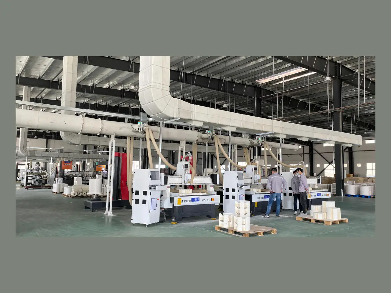
CNC machining of a drawing-based ceramic fiber component

01Drawing preparation guide

Ceramic fiber part drawing checklist

Prepare a clear ceramic fiber part drawing with material, temperature, critical dimensions, tolerances, openings, interfaces, quantity and revision data.

Revisiondrawing identification
Criticaldimensions and tolerances
Interfacesopenings and mating parts

02Overview

Mark the material grade, operating temperature, critical geometry, interfaces, tolerances, surface requirements, units and drawing revision. Unknown values can be identified clearly for discussion before quotation.

03Technical information

Show the dimensions and conditions that control fit, heat and manufacturing.

A useful ceramic fiber drawing identifies the component, operating conditions, critical geometry, mating interfaces, tolerances, openings, surface requirements, revision and quantity. Mark unknown values clearly instead of estimating them.

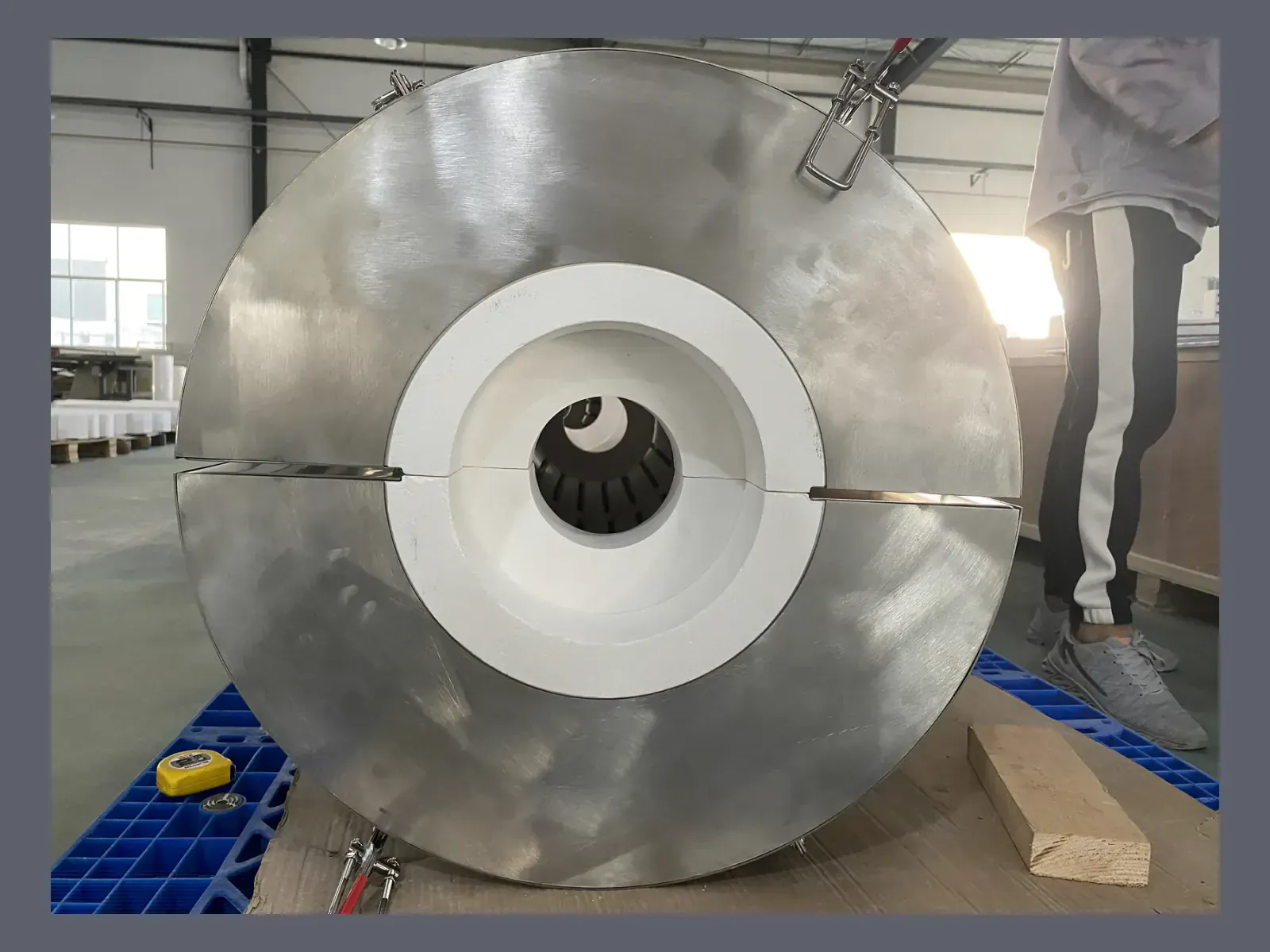
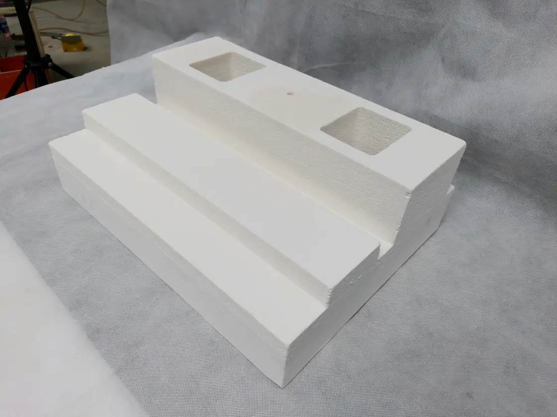
Machined ceramic fiber bores, slots and profiles
01

Provide clear views and dimensions

Use enough orthographic, section and detail views to define the part without hidden geometry. Dimension the hot face, outer envelope, bores, wall thickness, openings, grooves and locating surfaces from stable reference points.

  • Overall and internal dimensions
  • Sections through bores and grooves
  • Reference datums and critical-to-fit dimensions
Drawing-controlled heating-element grooves and interfaces
02

Add material and operating conditions

State the product family or required function, normal and peak temperature, atmosphere, cycling and mechanical exposure. If grade or density is unknown, mark it as not yet selected and provide the operating conditions.

  • Material form or functional requirement
  • Temperature, atmosphere and cycle
  • Density, surface or handling needs
Ceramic fiber component sections arranged for inspection
03

Mark interfaces and tolerances

Identify features that mate with metal shells, process tubes, elements, sensors, doors, anchors or other insulation. Apply tolerances only where fit or assembly requires them, and distinguish critical values from references.

  • Mating and mounting features
  • Element, lead and sensor paths
  • Critical tolerances and reference dimensions
Ceramic fiber board technical selection
04

Identify revision and supplied parts

Show the drawing number, revision, units, quantity and prototype or production stage. State whether the quotation should include machining, elements, shells, inspection records or export packing.

  • Drawing number, revision and units
  • Prototype and forecast quantity
  • Required parts and documents

04Selection table

Ceramic fiber drawing quality checklist

The checklist separates dimensions already defined on the drawing from tolerances, interfaces and inspection items that still require agreement.

Drawing areaIncludeAvoid
IdentityPart name, drawing number, revision, units and quantityFiles with no revision or unit system
GeometryOverall size, internal size, wall thickness, bores and sectionsRelying on photographs for hidden dimensions
InterfacesMounting, mating, elements, leads, sensors and openingsTreating connected equipment as outside the drawing
TolerancesCritical-to-fit values and reference datumsApplying tight tolerances to every dimension
Operating conditionsTemperature, atmosphere, cycle and mechanical exposureSelecting material from temperature alone
Included componentsForming, machining, surface, heating, shell and recordsLeaving supplied parts and buyer-installed parts unspecified

05Product selection steps

Prepare one clear drawing for quotation, prototype and repeat production.

A revision-controlled drawing gives engineering, manufacturing, inspection and purchasing the same dimensions and interfaces.

Ceramic fiber blanket technical selection
  1. 01

    Define the component function

    Identify the equipment, insulation role, operating conditions and the parts required from SYNTHE.

  2. 02

    Complete the drawing

    Add views, sections, dimensions, interfaces, openings and critical tolerances.

  3. 03

    Mark unknowns and options

    Call out material, density, surface or electrical decisions that still need to be confirmed.

  4. 04

    Confirm the correct revision

    Check the drawing number, units, prototype or batch quantity and required documents.

08Technical FAQ

Ceramic fiber drawing preparation questions.

01Which drawing formats can I send?+

You can send a 2D PDF or CAD drawing, STEP model, marked sketch, measured sample or clear photographs. Critical dimensions are recorded before custom production.

02Should every dimension have a tight tolerance?+

No. Mark the dimensions that control fit, assembly or function. Unnecessary tight tolerances can add cost without improving the application.

03What if the material grade or density is unknown?+

Describe the operating temperature, atmosphere, cycle, component dimensions and mechanical exposure, and mark grade or density as not yet selected.

04Can one drawing include heating elements and a metal shell?+

Yes. The drawing can include the ceramic body, elements, leads, terminals, sensors, shell, brackets and other required interfaces.

10Specification support

Prepare a drawing that clearly marks the dimensions that control fit.

Include datums, critical tolerances, holes, grooves, surface treatment, material grade, density and the intended mating or installation condition.