
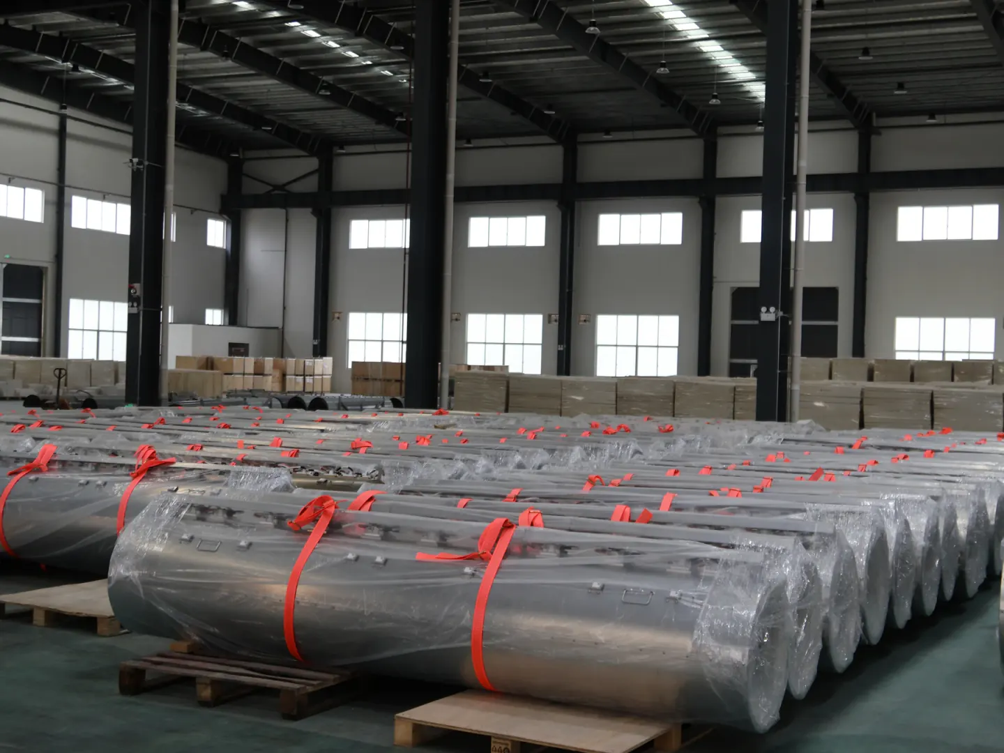
Thermal zones
List the start position and length of every main, end or guard zone, then place the associated sensor and control channel.
- Main and guard zones
- Zone boundaries
- Sensor and control locations
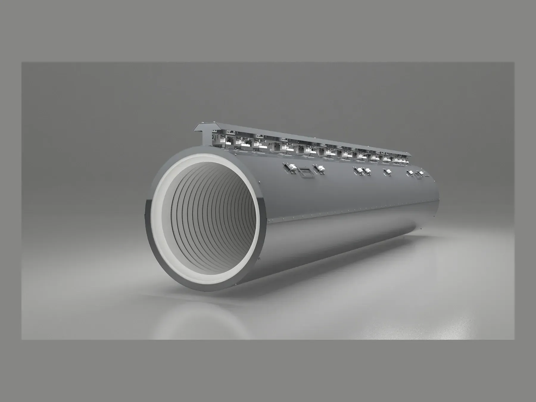
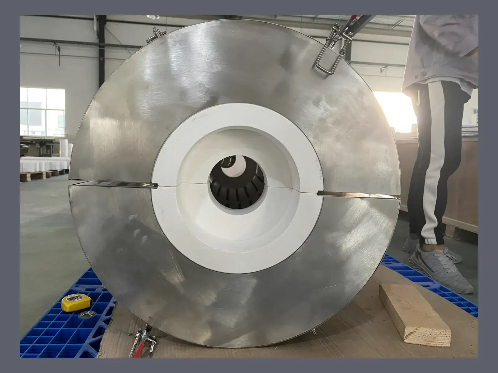
01Application
Multi-zone ceramic fiber heating assemblies for semiconductor diffusion equipment, made to the required tube diameter, heated length, zones, supports and terminals.
02Overview
SYNTHE supplies the insulated multi-zone heating assembly that surrounds the customer's process tube; it is not the quartz process tube itself. Heated length, zones, supports, electrical circuits and equipment interfaces are stated on the production drawing.
03Equipment requirements
In semiconductor diffusion equipment, the ceramic-fiber heater surrounds—not replaces—the quartz process tube. Its drawing must identify process-tube clearance, heated and overall length, main and end zones, section joints, supports, sensors, terminals and the direction used to install or remove each section.

List the start position and length of every main, end or guard zone, then place the associated sensor and control channel.

Mark body sections, joints, lifting points, installed supports and insertion direction against the equipment envelope.

Assign element type, voltage, power, circuit grouping, terminals and lead direction to each identified zone.
04Selection table
A quotation can be prepared from the process-tube dimensions, operating temperatures, heating zones, electrical supply and equipment interfaces.
| Input group | What to provide | Why it matters |
|---|---|---|
| Process tube | Material, outside diameter, length and support | Sets the internal geometry and clearances |
| Operating temperatures | Normal and maximum temperature, zone lengths and operating cycle | Guides material selection and heating-zone arrangement |
| Electrical | Voltage, power, element preference and control channels | Defines element and terminal architecture |
| Equipment integration | Outer envelope, orientation, supports and service access | Controls assembly, shipment and installation |
05Specification sequence
The heater drawing records the process-tube relationship, physical sections, electrical zones and connection points rather than relying on one catalogue diameter.

Record process-tube diameter, heater clearance, orientation and the maximum installation envelope.
Dimension body sections, active zones, end regions, joints, supports and sensor positions.
Record voltage, power, circuit, lead direction and terminal location for every identified zone.
Check drawing dimensions, circuit values and assembly condition before wooden-case packing.
06Related products
See heater construction, product views and required RFQ inputs.
View page →See the forming, machining, electrical-check and packing stages used for long heater assemblies.
View page →Attach the tube dimensions, zones, electrical data and installation envelope to the RFQ.
View page →07Heater drawing

08Technical FAQ
Yes. Project drawings, furnace details and process information are handled confidentially between the parties.
Yes. Zone count, lengths, voltage, power, element system, terminal arrangement and control boundaries are designed as one electrical architecture.
A standard export wooden case is used, with internal support and protection adapted to the assembly geometry and shipment requirements.
09Related information
10Application inquiry
Tell us which part of the equipment you need supplied, its operating conditions, approximate dimensions and quantity. Our team can help with the next material or heating-system decision.
With your permission, we use Google Analytics to understand website use. You can refuse analytics and still browse or send an inquiry. Privacy policy