
Working volume and outer envelope
State internal width, height and depth as well as the maximum external dimensions. Include the door overlap, threshold, supports and any restricted area around the furnace casing.

01Laboratory & heat treatment
Integrated and assembled ceramic fiber box chambers with custom doors, frames, openings and heating-element layouts.
02Overview
Muffle and box chambers are supplied as a formed hot-face body, an assembled chamber set or an element-integrated heating component. Quote data should separate the internal working volume from the maximum outer envelope and identify the door interface, hearth or base, vents, observation ports, thermocouple position, element material, voltage, power and terminal direction. These values determine whether a one-piece, sectional or framed construction is practical.
03Product views
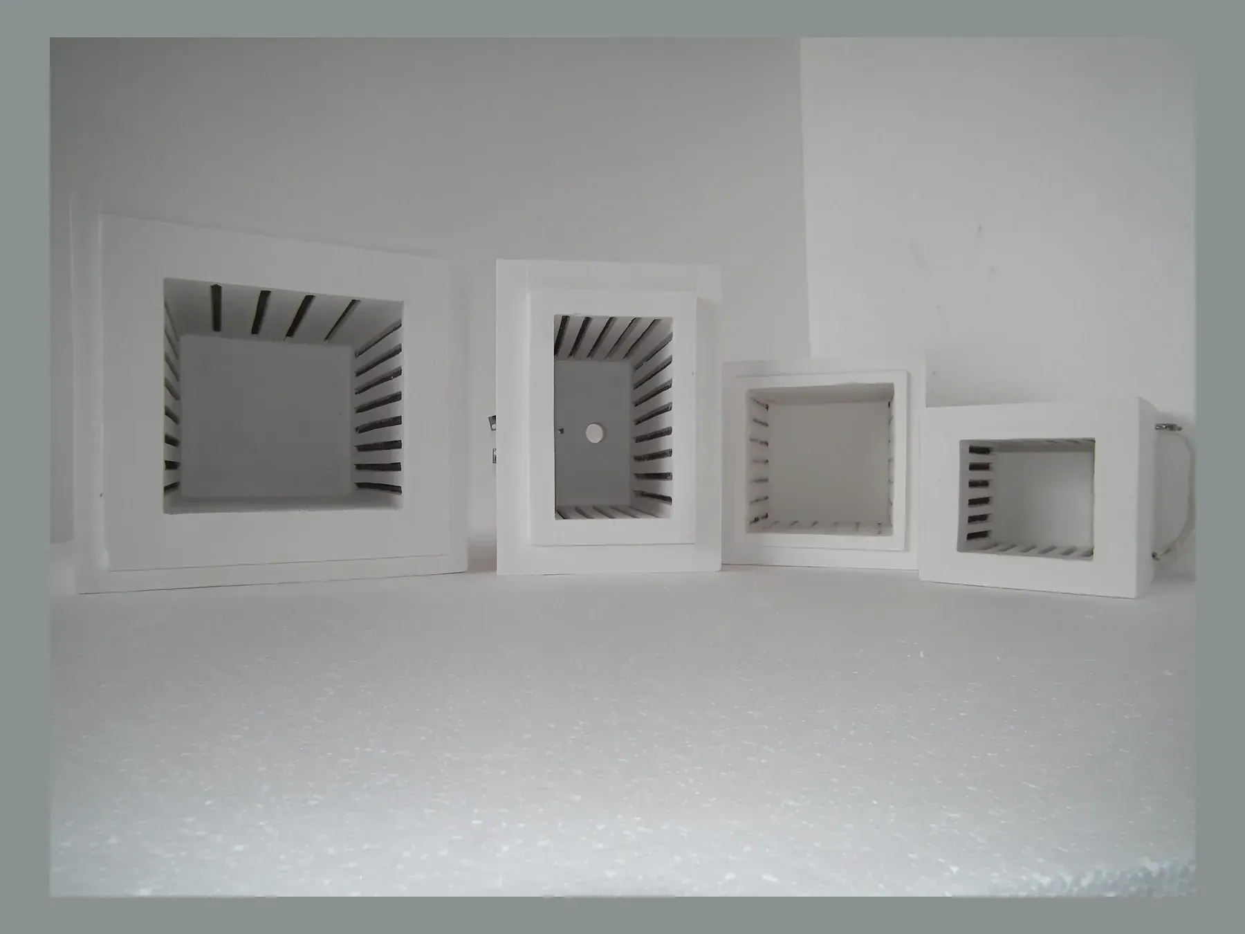
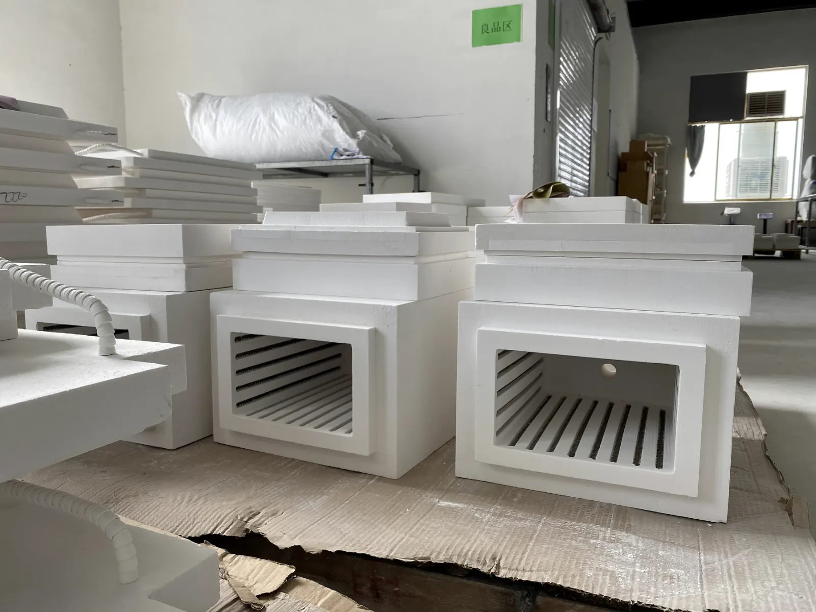
Box-type modules combine ceramic fiber insulation with a resistance-wire heating layout. Suitable configurations can be specified for continuous operation up to 1350°C, depending on the element alloy, electrical loading and process atmosphere. Specify the usable hot zone and maximum outer dimensions separately. Reference module sizes below are in mm; the quotation drawing identifies the working space, wall thickness and outer envelope.
05Selection guide
A muffle furnace chamber quotation separates the usable hot zone from the outer installation envelope, then defines the wall build-up, door fit, temperature cycle and electrical interfaces. Record both internal and external dimensions instead of using a nominal chamber size alone.
State internal width, height and depth as well as the maximum external dimensions. Include the door overlap, threshold, supports and any restricted area around the furnace casing.
Provide normal and maximum operating temperature, ramp and hold pattern, cycle frequency, furnace atmosphere and typical load. These conditions determine the grade, wall construction and element selection.
Define voltage, power, phase, preferred element type, thermocouple position, vents, observation ports and lead direction. Mark each opening on the chamber drawing.
06Custom engineering
Send the internal chamber size, maximum outer dimensions, operating cycle and electrical supply. We match the material grade, wall construction, element layout, leads and terminals to those requirements.
07Application fit
Low-mass chamber sets for testing, ashing, sintering and general heat treatment.
Application details ↗Drawing-led chambers for batch equipment, replacement projects and OEM production.
Application details ↗Thermocouple ports, vents and other openings can be positioned around the furnace hardware and available wall thickness.
Application details ↗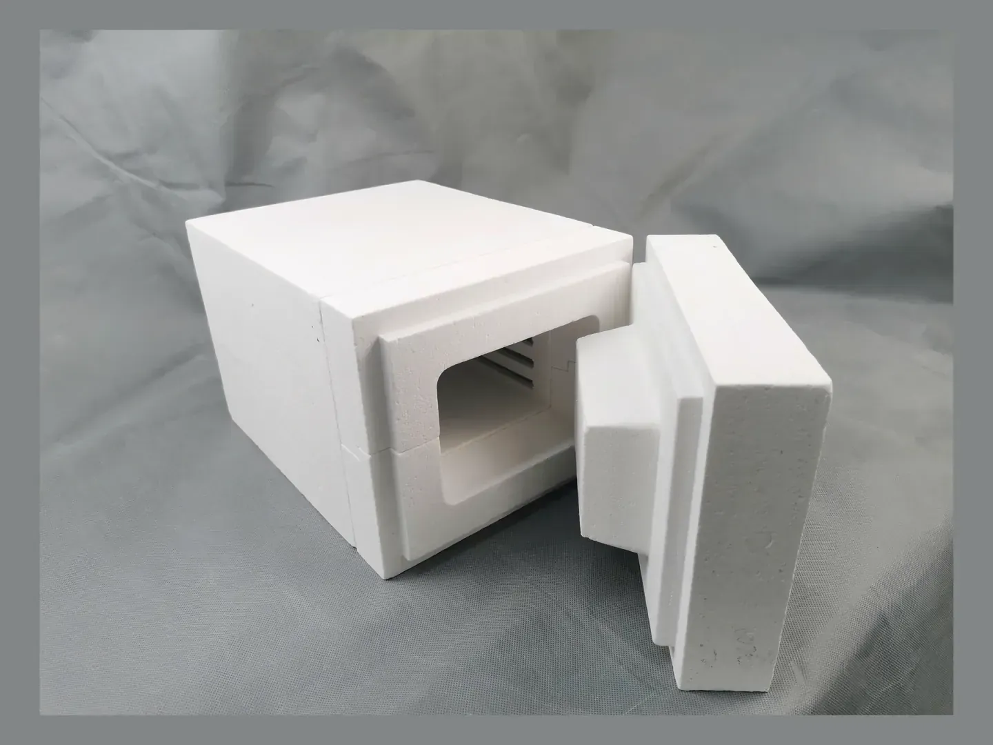
ProjectProduct configuration
This rectangular muffle chamber has a 400 × 300 × 300 mm working space, a 1500-grade ceramic fiber body and spiral heating elements mounted along the side walls.
The size table covers compact and larger box-furnace chambers. Other dimensions can be made from a drawing or measured sample.
Choose a formed body or a matched multi-piece chamber according to size, access and manufacturing requirements.
A single chamber can be used to check fit and electrical details before repeat production.
08Product FAQ
Yes. A drawing, marked-up photo or reference sample can be used to confirm dimensions, openings, element layout and mounting interfaces.
No. The standard-size list is a reference. Internal dimensions, wall thickness, external envelope and door structure can be customized.
Yes. Element type, distribution, voltage, power, lead exits and terminal arrangement are engineered as part of the complete chamber design.
Yes. MOQ can be one unit or a sample, followed by repeat production after validation.
09Related information
10Product quotation
Send the product dimensions, operating temperature and quantity. For a heated assembly, add the available voltage and power; a drawing or sample photo can help define the rest.
With your permission, we use Google Analytics to understand website use. You can refuse analytics and still browse or send an inquiry. Privacy policy