Installation and operating conditions
Provide the board location, normal and peak temperature, atmosphere, cycle and required heated area.
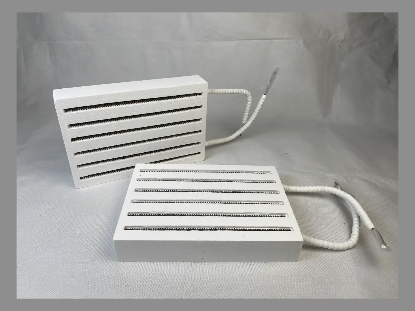
01Integrated resistance-wire heating
Custom ceramic fiber heating panels with resistance-wire layouts, lead exits, openings and mounting details made to the furnace drawing.
02Overview
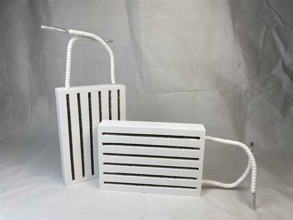
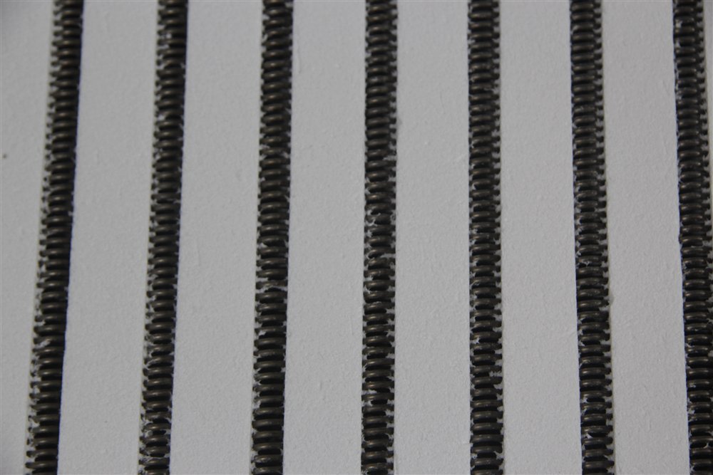
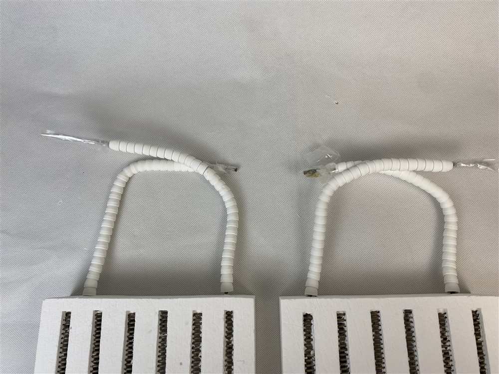
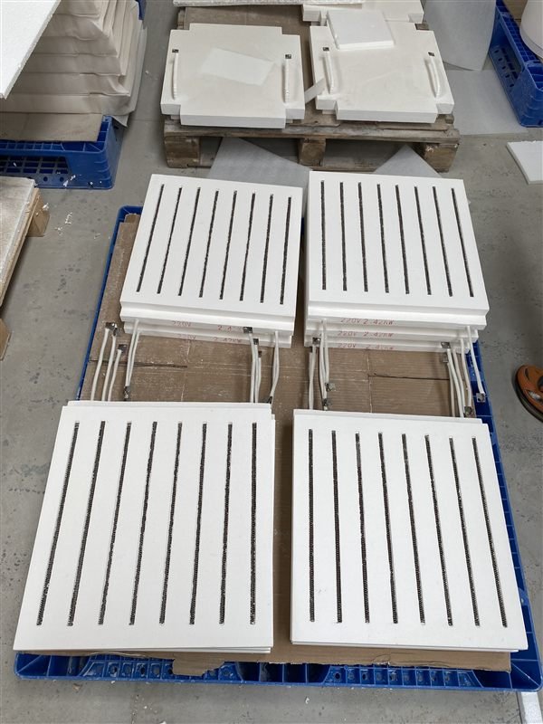
A ceramic fiber heating panel combines the insulation body and resistance-wire layout in one made-to-drawing component. Specify the board outline, thickness, heated area, mounting points, openings, groove pattern, wire retention, lead exits, terminals, voltage, power, circuits and thermocouple position. Supply can include the formed ceramic fiber body alone or the completed heating panel for final electrical and mechanical installation by the furnace manufacturer.
03Product views


04Specifications
Resistance-wire panel configurations can be specified for continuous operation up to 1350°C, subject to the selected wire alloy, electrical loading and atmosphere. The panel outline, thickness, groove pattern and lead exits are confirmed on the production drawing. Reference panel sizes below are length × width × thickness in mm; custom sizes are also available. Compare grooved, surface-mounted and embedded wire arrangements in the heating-element layout guide.
05Selection guide
The heating panel must fit the furnace opening and available installation space. Provide the heated area, maximum outer dimensions, openings, mounting points, resistance-wire grooves, leads and terminals.
Provide the board location, normal and peak temperature, atmosphere, cycle and required heated area.
Provide voltage, power, circuit grouping, target heating pattern, thermocouple position and preferred lead direction. These inputs determine groove layout and connection interfaces.
Show the outer dimensions, mounting holes, retaining features, openings and clearance around the board. State whether it must be removable as a one-piece replacement.
06Custom engineering
A heating-board RFQ should state the heated area, maximum outer dimensions, mounting and sensor openings, voltage, power, circuits, resistance-wire type, lead direction and terminal clearance. These values are recorded on the production drawing with the groove and connection layout.
07Application fit
Flat or shaped heating panels for compact working zones and replacement heating assemblies.
Application details ↗Heating panels can be reproduced from an equipment drawing or measured sample together with the electrical data.
Application details ↗Element grooves, leads and mounting points are positioned to fit the surrounding enclosure.
Application details ↗
ProjectProduct configuration
Flat and paired ceramic fiber heating panels use resistance-wire grooves and protected connection leads matched to the heated area.
Flat, paired and shaped heating panels are made to the furnace interface.
Element grooves, leads and terminal direction are built into the ceramic-fiber body.
Single replacement panels and repeat OEM quantities are both available.
08Product FAQ
Yes. Send the existing part or clear photographs with dimensions, voltage, power and lead positions. The finished dimensions and electrical layout are then recorded for production.
Yes. Order the formed ceramic fiber body alone or a complete heating panel with the specified resistance wire, leads and terminals.
Yes. Mounting holes, sensor ports, process openings, grooves and special profiles are manufactured from the furnace drawing.
Yes. MOQ can be one unit or a sample, followed by repeat production after the dimensions and electrical specification are approved.
09Related information
10Product quotation
Send the product dimensions, operating temperature and quantity. For a heated assembly, add the available voltage and power; a drawing or sample photo can help define the rest.
With your permission, we use Google Analytics to understand website use. You can refuse analytics and still browse or send an inquiry. Privacy policy