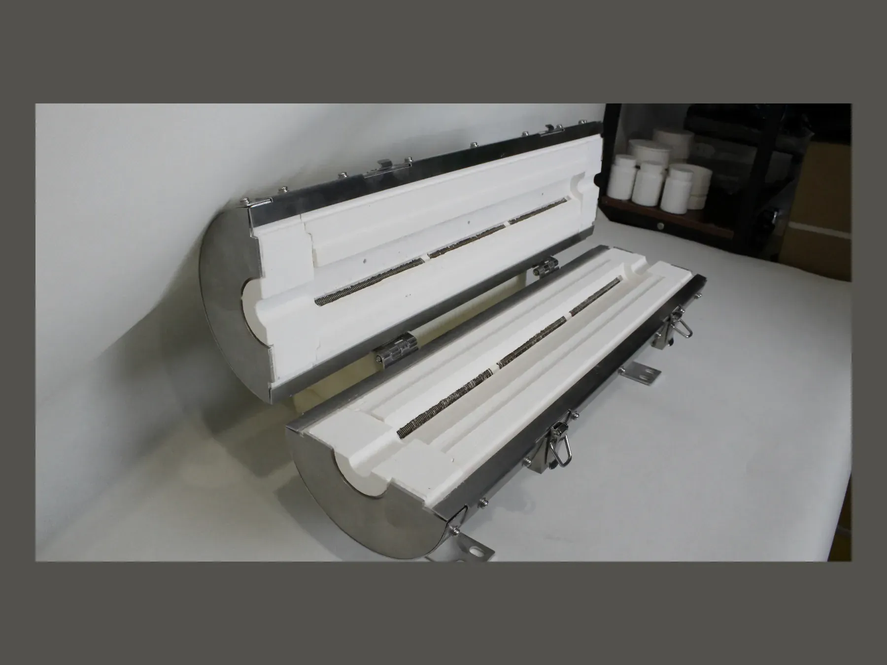
Embedded resistance-wire grooves inside a ceramic fiber furnace chamber

01Furnace heating-element guide

Embedded heating-element layout guide

Compare grooved, surface-mounted and embedded resistance-wire layouts for custom ceramic fiber furnace chambers and heating panels.

3element layouts compared
V / Welectrical inputs to define
Drawingelement and interface details

02Overview

Element position changes the chamber profile, wire exposure, heat transfer, support and maintenance access. Select the layout from the operating temperature, element material, surface loading, voltage, power, circuits, atmosphere, chamber dimensions, leads and terminals, then record it on the production drawing.

03Technical information

Choose the resistance-wire layout with the ceramic fiber chamber, not after it.

Element position changes the chamber profile, wire exposure, heat transfer, lead direction and maintenance access. Three common constructions are available: wire retained in formed grooves, wire mounted close to the chamber surface, or wire embedded beneath a ceramic fiber surface layer. Operating temperature, element material, electrical loading, atmosphere, chamber dimensions and service method determine the applicable construction.

Ceramic fiber furnace chamber with controlled internal geometry
01

Grooved resistance-wire layout

Resistance wire is seated in formed ceramic fiber grooves. Groove width, depth and pitch are specified with the wire support, retention and lead exits.

  • Wire seated in a formed groove
  • Groove dimensions matched to the element
  • Retention and lead exits specified together
View ceramic fiber heating panels →
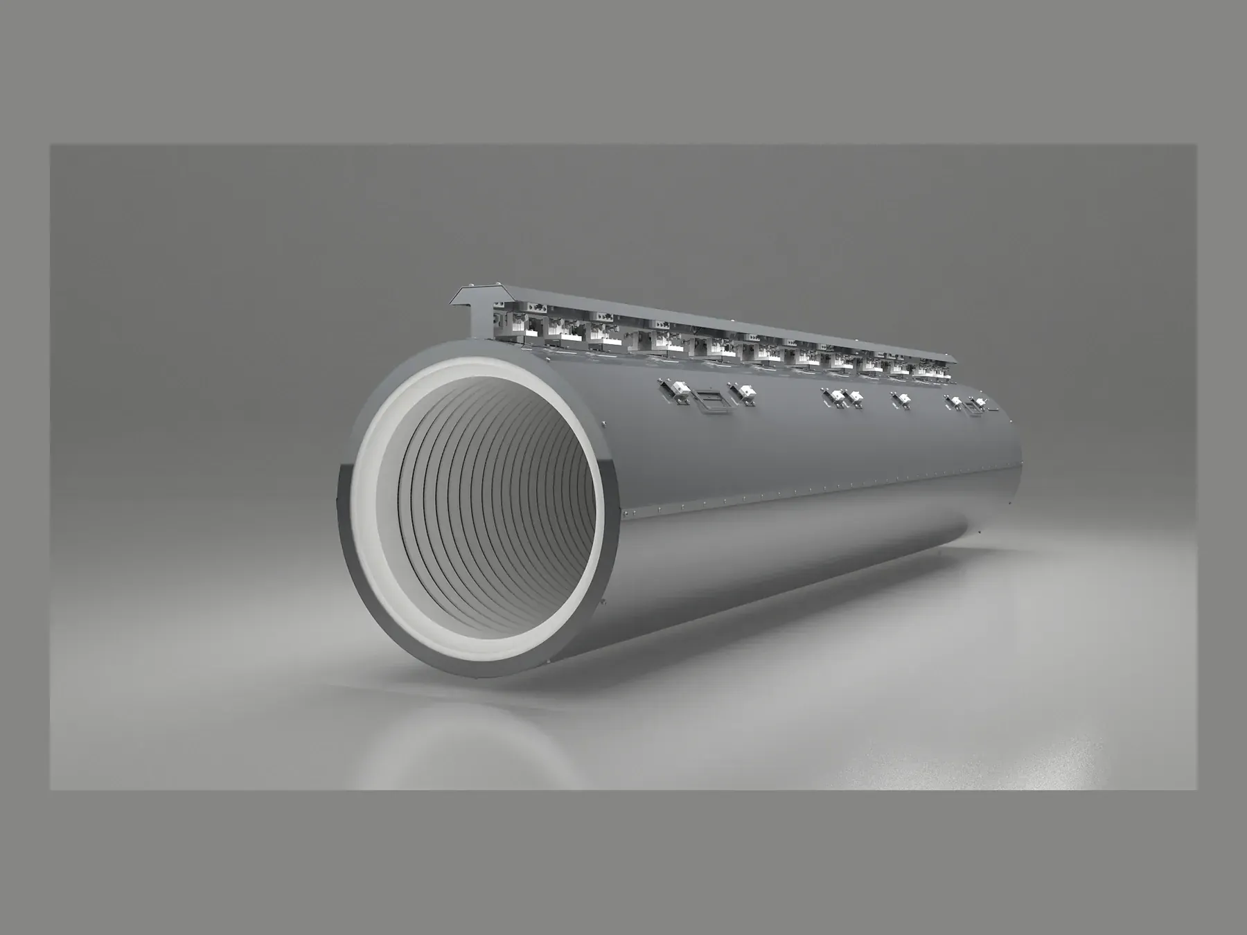
Multi-zone heating-element route within a large furnace assembly
02

Surface-mounted resistance-wire layout

The wire follows the inner chamber contour close to the heated surface. Element exposure, support points, spacing, leads and electrical connections must fit the chamber profile.

  • Element close to the inner chamber surface
  • Support and groove relationship
  • Heating pattern coordinated with the chamber
View element engineering →
Integrated furnace assembly with ceramic fiber hot face and heating elements
03

Embedded resistance-wire layout

A ceramic fiber surface layer covers the element. Specify the covering thickness, element depth, body thickness, expected thermal response, inspection method and access required for replacement or service.

  • Element below a ceramic fiber surface layer
  • Body thickness and element depth specified
  • Drawing defines inspection, leads and terminals
View muffle chamber options →

04Selection table

Embedded heating-element layout comparison

Element material, electrical load, chamber grade, dimensions, atmosphere and operating conditions determine the final layout.

LayoutVisible constructionSpecification focus
Grooved or slottedWire seated in a formed grooveRetention, groove geometry, hot-face profile and lead exits
Surface-mountedWire follows the inner chamber profileElement support, exposure, heating pattern and chamber contour
EmbeddedWire below a ceramic fiber surface layerSurface-layer thickness, element depth, thermal response and service access

05Product selection steps

Complete the heating layout before manufacturing the chamber.

The production drawing records the chamber profile, element position, electrical inputs, leads, terminals, supports and inspection points.

Ceramic fiber board technical selection
  1. 01

    Provide operating conditions

    State working temperature, cycle, atmosphere, loading, heating-zone requirement and intended furnace use.

  2. 02

    Map the hot zone

    Confirm chamber profile, walls to heat, openings, thermocouple locations, supports and outer enclosure.

  3. 03

    Set electrical inputs

    Record element material, voltage, power, circuit grouping, leads, terminals and control relationship.

  4. 04

    Confirm the construction

    Check the element layout, groove or surface profile, drawing revision, inspection points and included components.

08Technical FAQ

Embedded heating-element layout questions.

01Which resistance-wire layout is best?+

The choice depends on operating temperature, chamber dimensions, element material, electrical load, atmosphere, thermal response, wire exposure and maintenance requirements.

02Can an existing chamber be reproduced with a different element layout?+

Yes, subject to the available chamber space and operating conditions. Send the dimensions, photographs and electrical data. SYNTHE checks the proposed groove paths, element lengths, lead exits and mounting clearances against the existing chamber.

03Can SYNTHE supply the ceramic body with installed elements?+

Yes. Order a formed ceramic body, an element-installed chamber, a ceramic fiber heating panel or a stainless-steel cased heating assembly after the dimensions and electrical inputs are confirmed.

10Specification support

Define the electrical and hot-face requirements before fixing the element layout.

Send the heated area, voltage, power, circuits, operating temperature, preferred element material, lead exits, terminals and sensor locations.