Embedded heating elements manufacturing process

01Custom engineering

Embedded heating elements

Specify heating-element material, groove pattern, voltage, power, zones, sensors, lead exits and terminals with the ceramic fiber chamber.

V / Welectrical starting inputs
1+ zoneselement and sensor layout
Customleads and terminals

02Overview

The element layout changes the ceramic-fiber body: groove depth and spacing affect the hot face, while circuits, sensors, leads and terminals require their own space and access. Provide the electrical values and chamber drawing together.

03Engineering details

The heating element and ceramic fiber body are designed together.

Element material, voltage, power, resistance, heated length and zone arrangement determine the groove pattern and support method. Terminal position, lead direction, thermocouple openings and service access are included in the chamber drawing before manufacture.

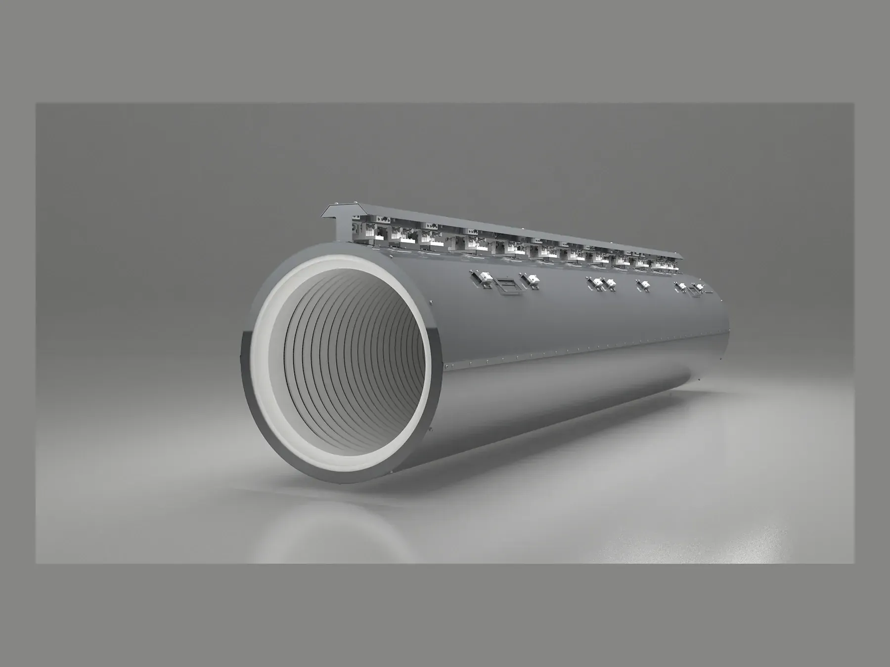
Large heater internal element layout
01

Electrical supply and circuits

Voltage, total and zone power, phase arrangement, resistance targets and controller channels establish the circuit.

  • Supply and phase
  • Zone-by-zone power
  • Resistance and connection plan
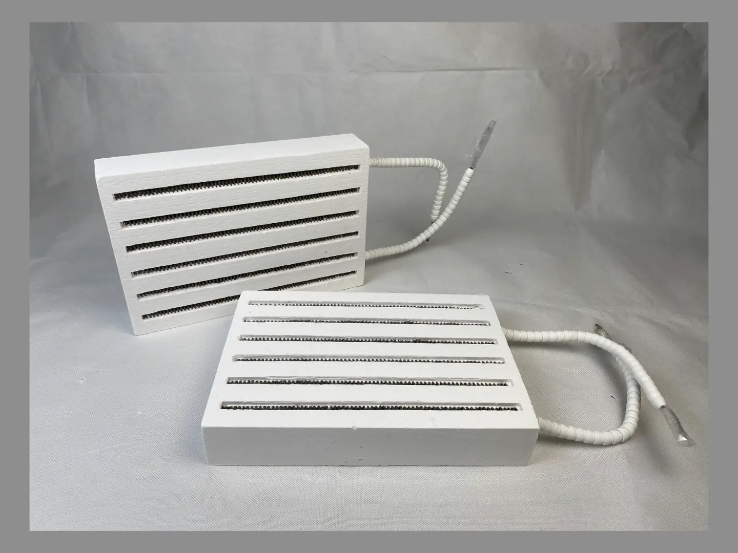
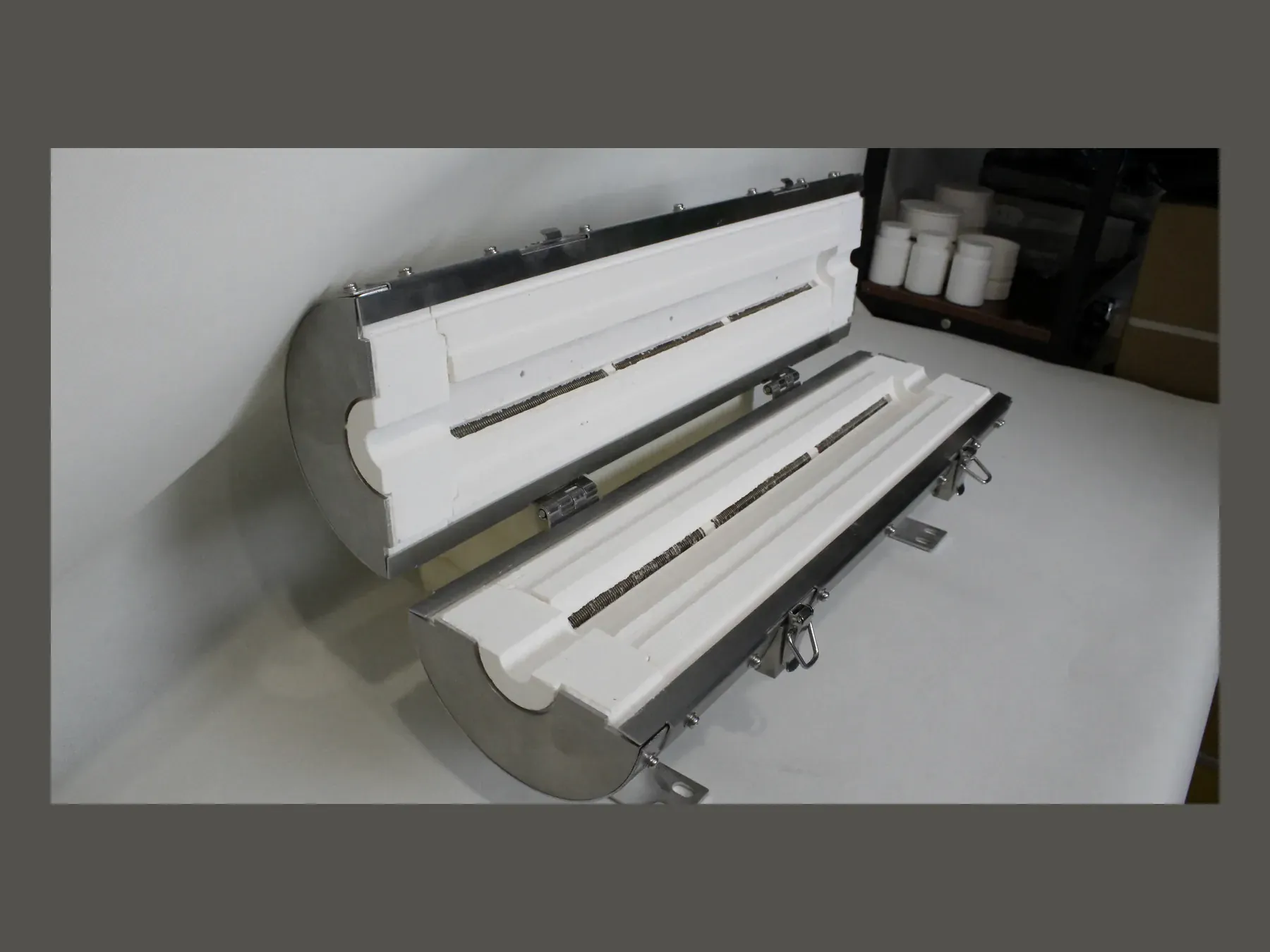
Ceramic fiber heating panels with visible resistance-wire routes and lead exits
02

Thermal layout

Hot-zone length, uniformity objective and end compensation guide element distribution.

  • Main and guard zones
  • Pitch transitions
  • Sensor relationship
Completed compact heating assemblies
03

Mechanical retention

Grooves, pins, supports and lead protection are selected for the chamber geometry and service method.

  • Exposed or recessed elements
  • Support spacing
  • Terminal and lead clearances

04Selection table

Electrical information for quotation

Send the values already fixed by the furnace design. Unknown items can be identified clearly instead of estimated.

InputInformation requiredEffect on the chamber
Power supplyVoltage, phase and frequencyCircuit and terminal arrangement
Heating requirementTotal power, zone power or required heat-up behaviorElement size, length and distribution
ControlZone count, sensors and controller channelsZone breaks and lead exits
InstallationTerminal space, cable direction and service accessExternal interfaces and protection

05Design and production steps

Confirm the circuit before machining the element grooves.

The electrical layout and chamber drawing use the same revision so changes to the bore, hot zone or openings are reflected in the element arrangement.

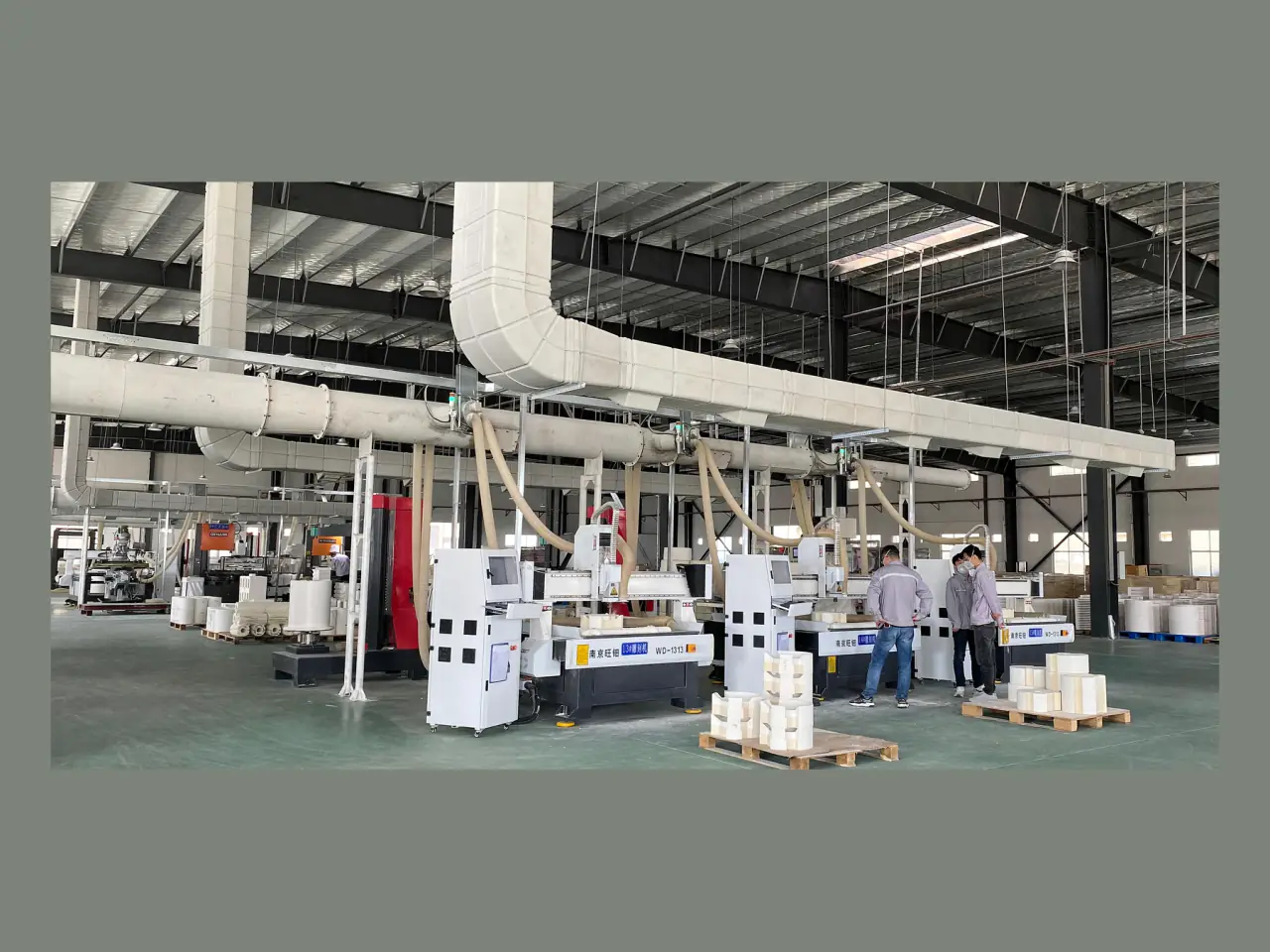
CNC workshop for ceramic fiber components
  1. 01

    Set temperature and supply

    Confirm the operating temperature, voltage, power, phase and control zones.

  2. 02

    Lay out the element

    Define element material, path, pitch, supports and zone transitions.

  3. 03

    Coordinate the body

    Resolve grooves, ports, sensors, leads, terminals and clearances.

  4. 04

    Inspect the assembly

    Apply resistance, wiring, dimensions and visual checks as relevant.

08Technical FAQ

Heating-element integration questions.

01Can SYNTHE select the element system?+

Yes. Provide the electrical supply, operating temperature, chamber dimensions, heating cycle and control arrangement. These inputs determine the element material, geometry, circuit connections and lead layout.

02Can elements be divided into independent zones?+

Yes. Each zone needs defined length, power or performance objective, sensor relationship, terminals and control channel.

03What electrical checks can be included?+

Depending on the product, inspection records can include element resistance, circuit connections, insulation-related checks and visual confirmation of terminals and leads.

10Custom engineering

Develop the heating-element layout around the required thermal zone.

Provide hot-face geometry, voltage, power, circuits, target temperature uniformity, element preference, lead direction and terminal limits.